Week 2: May 15th - 21st
- persaudpremnauth
- May 21
- 2 min read
Updated: May 21
Individual Log - Prem
An initial dual comparator circuit was designed (fig. 1) and built to test the regulation capabilities of the valves to validate that the water temperature can be effectively modulated since this valve type offers minimum feedback and control.
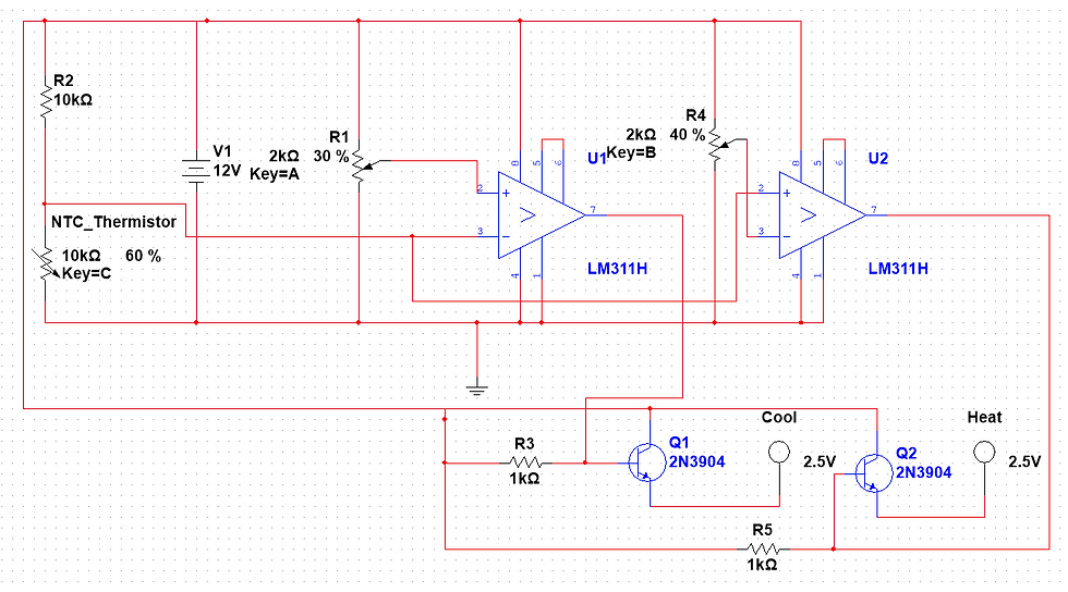
The reasoning for two comparators was to hopefully create a "dead zone" where both valves would be at rest. This circuit unfortunately did not work because the ball valves kept seeking even when both comparators were off. This was discovered to be a logic error that was developing inside of the ball valves that could only be rectified by removing each output when the other one was active. This issue was solved with a new circuit that replaced the transistors in the output stage with relays(fig. 2).


Figure 2: Dual Relay Driven Valve Actuator
With this circuit, the valves were now actuating and resting inside of the dead zone during artificial testing, but when connected to an actual faucet, by the time the comparator circuit was able to detect and correct temperature variations, the valves had already fully actuated, which created a system that just opened and closed the valves infinitely with no logic.
Methods for limiting valve actuation speed were tried, including regulating voltage and current, but both would caused them to malfunction below a certain threshold. This made it apparent that controlling the duty cycle of the valves was necessary.
A new circuit (fig. 3) was designed, this time including a 555 timer designed with an ultra low duty cycle connected to a single comparator.


Figure 3: Duty Cycle Controlled Valve Actuator
The timer circuit provides power to the valves for 100mS every 3 seconds. This creates a duty cycle of around 3 percent, which minimizes valve movement, while the 3 second interval allows for the new temperature to be properly registered to the circuit before the valves are pulsed again.
Since one of the comparators was removed, the valves will never completely park, but the extended time period counteracts this by minimizing oscillations. A single comparator also increases precision by completely removing the dead zone span.
To simulate the most extreme scenarios, both taps were opened all the way, and the temperature of the comparator was calibrated to the steady state temperature of 95F. The hot water was then abruptly shut off, making it impossible to calibrate the system. The circuit took exactly 40 seconds to detect this and shut the cold water off completely. The hot water tap was then opened back up all of the way, and it took another 40 seconds for the circuit to recalibrate the output to 95F.
If either faucet tap is placed in a partial position, it would adjust within around 30 seconds, but the valves struggle if the water pressure is reduced too much. This should be corrected by integrating the thermometer directly, in addition to the higher precision of the MCU, but it is not possible in this stage to validate yet.
Comments