Final Testing & Results
Valve Regulator Engineering Requirements
Engineering Requirement #1: Valve Regulator
“The Smart Water Faucet shall…” use temperature set by the user on the thermostat to preemptively regulate water temperature. ”
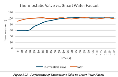
For this requirement, a thermostatic valve was used to create a baseline for comparison and performance. Both units were set at exactly 100 degrees fahrenheit and ran for 2 minutes. The comparison of the results is shown in the chart below. The only modification made to the testing environment was submersing both water lines in a bucket of ice and water maintained at 60F to replicate a more realistic scenario for a typical purge cycle.
Because of the circulation pump, the Smart Water Faucet had the initial advantage of being closer to the target temperature, and achieved it between 15 to 20 seconds while the thermostatic valve reached this target after 55 seconds. The thermostatic valve achieved a steady state temperature of 105F while the Smart Water Faucet fluctuated around the goal temperature of 100F. The minimum and maximum values of the Smart Water Faucet during steady state were 98 and 103F, which yielded a tolerance of 5 degrees.
Another performance metric that was checked was how quickly the Smart Water Faucet responds to changes to the temperature request. After it achieved a steady state of 105F, the temperature request was reduced to 95F to see how long it took to react. Although the system eventually reached the requested temperature, it took almost a full minute. This is probably related to the static duty cycle, which should be varied to cater more towards the temperature differential.
The pump was also successful in its purpose, with the only observation being that the initial purge cycle can take up to a full minute, but subsequent purge cycles staying under 30 seconds.

Engineering Requirement #2: Valve Regulator
“The Smart Water Faucet shall…”electrically sustain most or all of its operation via a built-in turbine generator.
This requirement was not met because the turbine generator did not produce sufficient power, most likely due to the aerator which reduced the water flow rate by 30%, and the fact that its final placement was on a single water line instead of the blended output, which means that it can only generate power in low amounts, and only if cold water is requested.
Engineering Requirement #3: Valve Regulator
“The Smart Water Faucet shall…” be able to detect leaks and close both valves in addition to sending a leak message to the thermostat to protect against property damage.”
For engineering requirement 3, the faucet was opened, and a bottle of water was placed in the valve enclosure compartment. The Smart Water Faucet was able to detect the water intrusion immediately and successfully close the valves within 13 seconds. Although this passes the requirement, the protocol of closing the valves will not completely protect the user from water intrusion, because if any joints or attachments before the valve fail, they will not stop the water flow. Placing the valves as the first point of contact would have mitigated this to an extent, but the circulation pump presented a challenge to this due to its nonsymmetrical design.
Engineering Requirement #4: Valve Regulator
“The Smart Water Faucet shall…have a waterproof enclosure for electrical components to prevent internal malfunction.”
For this requirement, water was placed in the valve controller compartment, and it was held overnight to see if there were any detectable leaks. This test was successful, and the unit was also tilted 15 degrees in every direction to validate the angle requirements of IPX2. It should be noted that the initial design goals were IPX7, but this was proved to be an excessive requirement due to the number of wires traveling through the compartments and maintaining accessibility of the product internals for servicing.
Engineering Requirement #5: Valve Regulator
“The Smart Water Faucet shall…continously send water temperature, flow rate, and battery voltage data to thermostat wirelessly.”
This requirement was partially met as the valve regulator is consistent in transmitting water temperature and battery percentage to the thermostat. The flow rate is consistently sent to the thermostat, however, the values become invalid during very slow flow rates.
Engineering Requirement #6: Valve Regulator
“The Smart Water Faucet shall…be completely contained, with only 3 or 4 connections for the faucet.”
This requirement was met, with the only external changes made to the product design requiring nipples if the faucet connections are female. The requirement for a splitter was also removed and replaced with screwing a cap on the unconnected line to seal it off instead.
Engineering Requirement #7: Valve Regulator
“The Smart Water Faucet shall…have the ability to be externally charged in cases of battery exhaustion.”
This requirement was successfully met by charging the product right before final testing and tracking the observed battery performance. The battery was around 75% charged at this point, and after being charged, maintained full charge throughout final testing.
Engineering Requirement #8: Thermostat
“The Smart Water Faucet shall…accept temperature request from user & send to valve regulator”
This requirement was met successfully and verified numerous times using a second MCU initially, and in final testing demonstrated consistent and accurate transmission of set temperature to the valve regulator. Code on the thermostat allows users to adjust the knob and waits approximately one second before sending the command.
Engineering Requirement #9: Thermostat
“The Smart Water Faucet shall…display requested temperature, water temperature, water consumption, leak detection & battery state of charge on an LCD screen.”
Initial verification and testing for this requirement was performed using the LightBlue app to adjust associated BLE characteristics to verify values were being accurately displayed over Bluetooth. Next a for loop was used to increment values one
by one to verify that each value would update with minimal delay. Final testing of this requirement was done with the valve regulator connected and water running through the system.
Actual temperature was tracked accurately, but with a small delay as the thermistor read and adjusted its voltage output.
Battery remaining displayed 100% with the battery fully charged, battery percentages were noted to be around 86% and displayed accurately on the thermostat LCD during testing phases performed in the open lab.
Water consumption was the only value that was not displayed accurately. When the faucet was turned on, the value began increasing by 1 gallon at a rate faster than intended.
Leak detection was successfully verified by pouring a bottle of water into the valve chamber (opposite of the electronics) to trip the moisture sensor. Once the moisture sensor detected the presence of water, the thermostat promptly cleared its screen and displayed a warning for leak detection and played a buzzing tone to alert the user.
Engineering Requirement #10: Thermostat
“The Smart Water Faucet shall…minimize power consumption when not in use."
This requirement was successfully verified before final testing using a multimeter and the LightBlue app. Using the BLE characteristic for “wake”, which is tied to the generator in the valve regulator, when the faucet is turned on OR if the potentiometer is turned when the faucet is off. The backlight and display will activate, when the faucet is turned off, the backlight and display turn off reducing the power consumption.
Engineering Requirement #11: Thermostat
“The Smart Water Faucet shall…Include an installation and operator’s manual.”
This requirement was fulfilled using short and concise instructions for installing the valve regulator underneath a household sink using minimal tools and extra parts. The manual also included basic instructions on how to operate the device, which simply consists of turning a knob, information about what warning features the device has, and other features. This manual can be found in this document in Appendix E.